[continued from previous message]
- Video jack (phono, providing composite video)
65XE/130XE/800XE features not present on the XE System Console:
- No Enhanced Cartridge Interface (ECI)
- NTSC/PAL versions: No Monitor port
- SECAM version: No Television jack
System initialization types supported:
- Cartridge: Press [Power] on the Console with cartridge inserted.
(disables BASIC and Missile Command)
- Atari BASIC, Missile Command, Self Test, Cassette boot, or Disk boot:
(boot cassette or boot disk may or may not require BASIC or cartridge)
Keyboard Held down while pressing [Power]:
Attached [Option][Select][Start] Result
---------------------------------------------
N N N N Start Missile Command
N N N Y Cassette boot, Missile Command enabled
N N Y N Disk #1 boot if present, BASIC enabled
N N Y Y Cassette boot, BASIC enabled
N Y N N Disk #1 boot if present, else Self Test
N Y N Y Cassette boot, BASIC/MC disabled
N Y Y N Start Missile Command
N Y Y Y Cassette boot, Missile Command enabled
Y N N N Disk #1 boot if present, BASIC enabled
Y N N Y Cassette boot, BASIC enabled
Y N Y N Start Missile Command
Y N Y Y Cassette boot, Missile Command enabled
Y Y N N Disk #1 boot if present, else Self Test
Y Y N Y Cassette boot, BASIC/MC disabled
Y Y Y N Disk #1 boot if present, BASIC enabled
Y Y Y Y Cassette boot, BASIC enabled
(table adapted from AtariAge post by Tomasz Krasuski, May 2014)
- Cassette boot further steps:
(System buzzer sounds.)
2. Press [PLAY] on the program recorder with boot cassette inserted.
3. Press [Return] on the Keyboard if present, else press [Start].
Versions of the XE System Console:
o Domestic version for NTSC M television (North America)
- 6502 MPU (Atari SALLY), C014806
- ANTIC NTSC 'E' version, C021697
- GTIA NTSC version, C014805
- No Monitor port
- Monitor Video Jack (phono) for composite video output
- Television jack for RF output
- TV Channel Selector switch on back of Console selects RF channel 2 or 3
- TV Switch Box and TV Cable both supplied with Console
o PAL versions for PAL B/G television (Europe) or PAL I television (UK)
- 6502 MPU (Atari SALLY), C014806
- ANTIC PAL 'B' version, C021698
- GTIA PAL version, C014889
- No Monitor port
- Monitor Video Jack (phono) for composite video output
- Television jack for RF output
- No TV Channel Selector switch
- TV output: RF channel 4 (PAL B version) or 36 (PAL G/PAL I versions)
- TV Cable supplied with Console
o SECAM version (France)
- 6502 MPU (Atari SALLY), C014806
- ANTIC PAL 'B' version, C021698
- FGTIA, C020120
- Monitor port is Atari SECAM 6-pin
- Monitor Video Jack (phono) for composite video output
- No Television jack
- No TV Channel Selector switch
- TV cable (Monitor port to SCART/Peritel) supplied with Console
The components of the XEgs were sold by Atari in several different packages, which are listed in the broader "kits" listing in this FAQ list.
(see Atari User v3n9 p.28 for a partial list of packages)
Manuals:
- Atari XE System Owner's Manual C100608 / C033514 (26 pages)
- Atari XE System Keyboard Owner's Manual C100609 / C033513 (99 pages)
The XE System Console was made by Atari Taiwan Manufacturing Corp.
------------------------------
Subject: 1.10) What is the Atari 800XE?
The Atari 800XE was announced (not by name at the time) in March 1987 in West Germany, and shipped later that year as a regional (West Germany, Austria, Switzerland) complement to the Atari 65XE and 130XE. The 800XE name was selected in a marketing attempt to capitalize on the recent and surprisingly swift final sellout of available inventory of new 800XL units. (The 800XE was never introduced in the U.S.)
The 800XE is identical to the common PAL B version of the 65XE, utilizing the same PAL 130XE motherboard with Enhanced Cartridge Interface (ECI).
The 800XE offers 64KiB RAM (62KiB usable), and has the Atari XL OS and Atari BASIC on ROM.
System initialization types supported:
- Atari BASIC: Turn on computer with no cartridge inserted and no powered
disk drive #1.
- Self Test program: Hold down [Option] while turning on the computer with no
cartridge inserted and no powered disk drive #1.
- Cartridge: Turn on computer with cartridge inserted. (disables BASIC)
- Cassette boot: (boot cassette may or may not require BASIC or cartridge)
1. - With BASIC or with cartridge (cartridge disables BASIC):
Hold down [Start] while turning on the computer.
- With no cartridge and without BASIC:
Hold down both [Start] and [Option] while turning on the computer.
(system buzzer sounds)
2. Press [PLAY] on the program recorder with boot cassette inserted.
3. Press [Return] on the computer.
- Disk boot: (boot disk may or may not require BASIC or cartridge inserted)
- With BASIC or with cartridge (cartridge disables BASIC):
Turn on computer with boot disk inserted in powered disk drive #1.
- With no cartridge and without BASIC:
Hold down [Option] while turning on computer with boot disk inserted
in powered disk drive #1.
Versions of the Atari 800XE:
o PAL versions for PAL B/G television (Europe)
- PAL 130XE motherboard (including ECI, but only 64KiB RAM)
- 6502 MPU (Atari SALLY), C014806
- ANTIC PAL 'B' version, C021698
- GTIA PAL version, C014889
- 16KiB Operating System ROM: XL OS Rev.3, C300717
- Atari BASIC Rev. C (8KiB ROM), C024947
- Monitor port is Atari 5-pin
- Television Jack for RF output
- TV Channel Select Switch: Either not present, or has no effect
- TV output: RF channel 4 (PAL B version) or 36 (PAL G version)
- TV Video Cable supplied with computer
Some images of the 800XE:
http://www.silicium.org/oldskool/atari/800xe.htm
Jindrich Kubec writes, "The problematic Chinese 800XEs with GTIA problems were manufactured in 1992."
The 800XE was made by Atari Taiwan Manufacturing Corp. (most units) and in China (late production 1991 or 1992 units).
------------------------------
Subject: 1.11) What were the Atari 1400XL, 1450XLD, 65XEP, and 65XEM?
Atari publicly introduced or announced several computers in the tradition of the 400/800/XL/XE series that ultimately never shipped.
The 1400XL was introduced by Atari, Inc. alongside the 600XL, 800XL, and 1450XLD at the June 1983 Summer Consumer Electronics Show (CES) in Chicago,
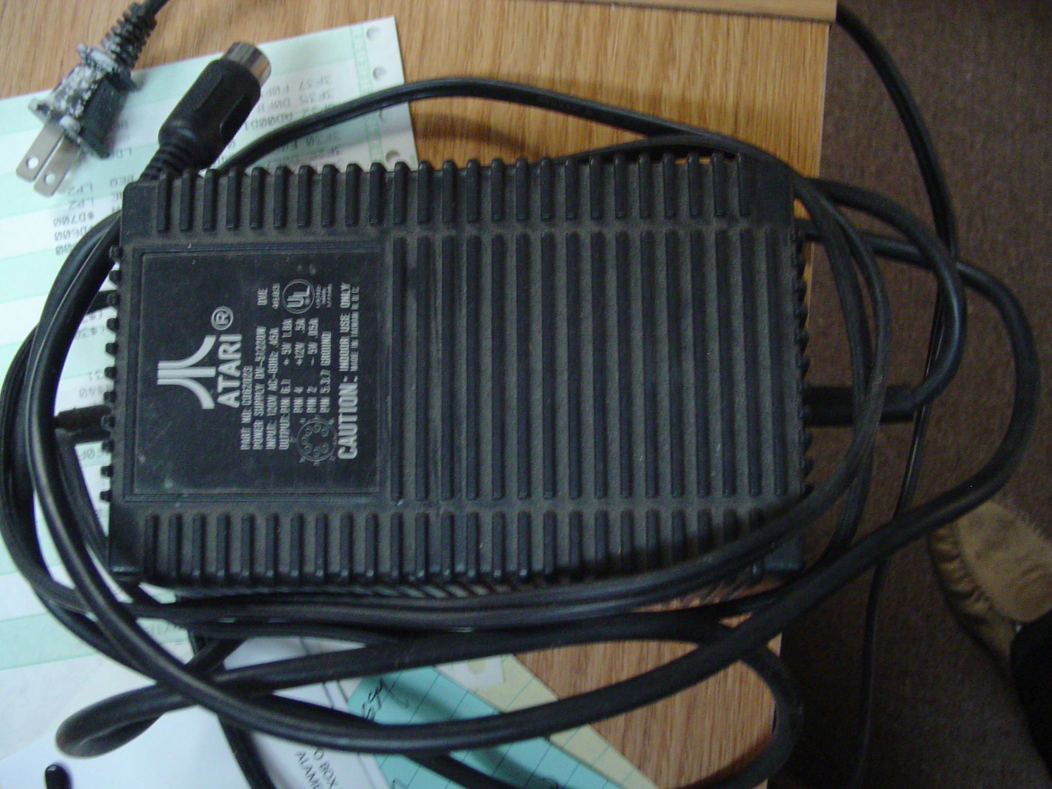
and promised to ship in September 1983. Expected to replace the 1200XL, and resembling the 1200XL in appearance, the 1400XL was to provide the features of the 800XL plus a built-in 300 baud modem with ModemLink software and a built- in speech synthesizer (Votrax SC-01). Earlier internal names at Atari for the 1400XL: "1201", "1200XLT". Power jack is a female DIN-7 270 Socket: pins 1,6 +5V; pin 2 -5V; pin 4 +12V; pins 3,5,7 GND. Uses a DC power supply (external adapter) rated for 22 watts such as Atari# C062023 (
https://mcurrent.name/powersupplies/62023.jpg) or equivalent. Prototype units exist, but the 1400XL (and the C062023) never shipped.
http://www.atarimuseum.com/computers/8BITS/XL/1400xl/1400.html
The 1450XLD was introduced by Atari, Inc. alongside the 600XL, 800XL, and 1400XL at the June 1983 Summer Consumer Electronics Show in Chicago, and originally promised to ship in October 1983. As introduced, the 1450XLD was
to provide the features of the 1400XL plus a built-in double-sided, dual/enhanced density 260KiB 5.25" floppy disk drive that would be 2.5 times faster than the 810 (connected directly to the computer's processor bus), with expansion space for a second disk drive. A revised 1984 design instead featured a double-sided, true double density 360KiB disk drive operating 5 times faster than in the 1983 design, and included the newer Silicon Systems SSI-263 (equivalent to the Votrax SC-02) speech synthesis chip. Atari continued to promote the 1450XLD by name through May 1984, and privately
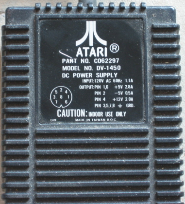
showed the 1984 design at the June 1984 CES. Earlier internal names at Atari for the 1450XLD: "6402", "1251", "1250", "1200XLD", "1250XLD". Also: "1450XL" (without internal disk drive). Power jack is a female DIN-8 270 Socket: pins 1,6 +5V; pin 2 -5V; pin 4 +12V; pins 3,5,7,8 GND. Uses a DC power supply (external adapter) rated for 45 watts such as Atari# C062297 (
https://mcurrent.name/powersupplies/62297.jpg) or equivalent.
Prototype units exist, but the 1450XLD (and the C062297) never shipped.
http://www.atarimuseum.com/computers/8BITS/XL/1450xld/1450xld.html
The 65XEP was previewed by Atari, Corp. alongside the introductions of the
65XE and 130XE at the January 1985 Winter Consumer Electronics Show in Las Vegas. The portable 65XEP was to provide the features of the 65XE, plus built-in 5" monochrome CRT display and 360KiB 3.5" disk drive. The 65XEP
never shipped, and possibly only the single original mockup display prototype unit ever existed.
http://www.cyberroach.com/cyromag/14/DSCN3934.jpg
The 65XEM was pre-announced by Atari, Corp. in advance of the January 1985 Winter Consumer Electronics Show in Las Vegas, but was never introduced. The 65XEM was to provide the features of the 65XE, plus advanced sound/voice synthesis capabilities thanks to the addition of the AMY Sound Processor chip. Eight voices giving rich music giving the following features: (Page 6 #14 Mar/Apr 85)
- Digital sample rate in excess of 30kHz. Over 60dB dynamic range.
- Fundamental Frequency Range of 4.8Hz to 7.8kHz -10 2/3 octaves.
- Fundamental Frequency Resolution of 1/64 semitones.
- Precise control of harmonic amplitudes. 64 harmonics.
No more than a handful of prototype 65XEM units may exist.
http://www.atarimuseum.com/computers/8bits/xe/xe_protos/65xem.html
------------------------------
Subject: 1.12) What are SALLY, ANTIC, CTIA/GTIA/FGTIA, POKEY, and FREDDIE?
Portions of this section derived from De Re Atari.
The internal layout of the Atari 8-bit computer is very different from other systems. It of course has a microprocessor (a 6502), random-access memory (RAM), read-only memory (ROM), and a peripheral interface adapter (PIA). However, it also has three special-purpose large-scale integration (LSI) chips known as ANTIC, one of CTIA/GTIA/FGTIA, and POKEY. These chips were designed by Atari engineers primarily to take much of the burden of housekeeping off of the 6502, thereby freeing the 6502 to concentrate on computations. While they were at it, they designed a great deal of power into these chips. Each of these chips is almost as big (in terms of silicon area) as a 6502, so the
three of them together provide a tremendous amount of power. Mastering the Atari 8-bit computers is primarily a matter of mastering these three chips.
6502 MPU -- MOS Technology MCS6502A or equivalent (400/800,most NTSC):C014377 ======== Atari SALLY (400/800,late NTSC & all PAL; XL/XE,all):C014806 The Atari 400/800 were designed around the MOS Technology MCS6502A (6502 rated for 2MHz) microprocessor unit (MPU). The MCS6502 primary designers were Chuck Peddle (architecture) and Bill Mensch (engineering), and it was introduced by MOS Technology in September 1975. MOS Technology was acquired by Commodore (CBM) in November 1976, and would later operate as Commodore Semiconductor Group (CSG). Before appearing in the Atari 400/800, the 6502 had already gained wide market acceptance in products including the Apple II and Commodore PET microcomputers, and the derivative 6507 was used in the Atari Video Computer System (VCS).
While the 6502 is not proprietary to Atari, the standard 6502 chips shipped in most Atari NTSC 400/800 computers were usually manufactured for Atari and have the Atari C014377 part number.
Later production NTSC 400/800 computers, all PAL 400/800 computers, and all of the Atari XL/XE computer models contain Atari's proprietary version of the
6502 chip. This chip was originally named SALLY by Atari engineers, but Atari Customer Support documents (Field Services Manuals) variously described it as "6502 (Modified)", "6502 Modified", "Custom 6502", or "6502C". Field Service Manuals published by Atari, Corp./Atari Corporation reverted to using the chip's original name, SALLY, while Atari, Corp./Atari Corporation XE consumer owner's manuals (unfortunately) continued to use "6502C" in reference to the SALLY 6502.
Several manufacturers produced the SALLY 6502 for Atari, including MOS Technology, Synertek, Rockwell, NCR, and United Microelectronics (UMC). It is important to note that chips marked "6502C" such as the MOS Technology MCS6502C, MOS Technology MPS6502C, Synertek SY6502C, Rockwell R6502C, or UMC UM6502C are NOT the Atari "6502C" but rather equivalents to the standard MCS6502 that are certified for 4MHz operation. Atari SALLY 6502 chips are never marked "6502C" but, other than the UMC UM6502I, always carry the Atari part number C014806.
In contrast to the MCS6502 and equivalents, the SALLY 6502 has the addition of a /HALT signal on pin 35. The SALLY 6502 also has a second R/W signal on pin 36 (in addition to pin 34). Pins 35 and 36 are not connected on the MCS6502 and equivalents.
The Atari's second microprocessor, ANTIC, must routinely interrupt the 6502 in order to utilize the processor bus for itself for direct memory access (DMA). /HALT on the SALLY 6502 facilitates this system design. Atari's earlier implementation of the same functionality in the 400/800 using the MCS6502 or equivalent requires a series of 4 additional chips that are unnecessary in computers designed for the SALLY 6502.
Other systems utilizing the Atari SALLY 6502 chip:
- Atari 5200
- Exidy Max-A-Flex coin-operated arcade conversion system
(embedded Atari 600XL): Astro Chase, Boulder Dash, Bristles, Flip and Flop
- Atari 7800
6502.org "the 6502 microprocessor resource":
http://www.6502.org/
ANTIC -- ANTIC NTSC (pre-'E'):C012296 ANTIC PAL 'A':C014887
===== ANTIC NTSC 'E':C021697 ANTIC PAL 'B':C021698
- C012296/C014887 shipped in the 400/800/1200XL and some 800XL units.
- C021697/C021698 shipped in the 600XL, some 800XL, and all XE units.
ANTIC ("AlphaNumeric Television Interface Controller" --FD100001 Rev.02 p.1-8) is a microprocessor dedicated to the television display. It is a true microprocessor; it has an instruction set, a program (called the display
list), and data. The display list and the display data are written into RAM
by the 6502. ANTIC retrieves this information from RAM using direct memory access (DMA). It processes the higher level instructions in the display list and translates these instructions into a real-time stream of simple instructions to CTIA/GTIA/FGTIA.
Specific ANTIC functions include:
- Object DMA (Direct Memory Access) control.
Two types of display DMA (uses 6502 halt for "cycle stealing"):
1) Playfield DMA - Execution of display list instructions in RAM.
2) Player-Missile DMA - Automatic fetching of player-missile graphics
data from RAM for CTIA/GTIA/FGTIA.
The ANTIC chip also generates DMA addresses for the (entirely automatic)
refresh of on-board dynamic memory RAM (DRAM). ANTIC versions C012296/
C014887 use an 8 bit refresh cycle counter, supporting DRAM chips including
those requiring 128 cycle/2ms or 256 cycle/4ms refresh (standard 16KiB and
64KiB DRAM chips). The C021697/C021698 ANTIC versions use a 9 bit refresh
cycle counter, supporting additional DRAM chips that require more refresh
cycles (standard 256KiB DRAM chips).
- NMI (Non-Maskable Interrupt) control. 3 types of NMIs on the Atari are:
1) Display List Interrupt (DLI)
2) System Reset (key)
3) Vertical Blank Interrupt (VBI)
- Vertical and Horizontal fine scrolling
- Vertical line counter (VCOUNT)
- Light pen / light gun position registers
- New values are stored when any one of the joystick trigger lines (except
jacks 1-3 on the 400) is pulled low by the pen/gun, which happens when
the light detector in the pen/gun detects the CRT electron beam.
- Horizontal value is the color clock count (with offset/wraparound),
yielding possible values from 0-227.
- Vertical value is the vertical line counter (VCOUNT) value, or the
number of scan lines divided by two, yielding possible values from 0-130
(NTSC ANTIC) or 0-155 (PAL ANTIC).
- WSYNC (wait for horizontal sync) command -- allows the microprocessor to
synchronize itself to the TV horizontal line rate
Other systems utilizing the Atari ANTIC chip:
- Atari 5200
- Exidy Max-A-Flex coin-operated arcade conversion system
(embedded Atari 600XL): Astro Chase, Boulder Dash, Bristles, Flip and Flop
ANTIC C012296 (NTSC) REV. D technical documentation by Atari:
http://preview.tinyurl.com/y8vlcvuq
CTIA/GTIA/FGTIA -- CTIA(NTSC):C012295 GTIA,PAL:C014889
=============== GTIA,NTSC:C014805 FGTIA(SECAM):C020120
CTIA = "Color Television Interface Adaptor" --FD100001 Rev.02 p.1-10
"Colleen Television Interface Adaptor" (probable original)
GTIA = "Graphics Television Interface Adaptor" --FD100001 Rev.02 p.1-10
"George's Television Interface Adaptor" (probable original)
FGTIA = "French Graphics Television Interface Adaptor" (probable)
Early NTSC 400/800 units shipped with CTIA. Later NTSC 400/800 units, all PAL 400/800 units, and all NTSC XL/XE and PAL XL/XE systems include GTIA. SECAM 800XL, 130XE and XE System Console units include FGTIA.
The NTSC versions of CTIA/GTIA were designed to interface with the NTSC
version of ANTIC. The PAL version of GTIA and the FGTIA were designed to interface with the PAL version of ANTIC.
The CTIA, GTIA, or FGTIA is the television interface chip. ANTIC directly controls most of the operations of the CTIA/GTIA/FGTIA, although the 6502 can also be programmed to intercede and control some or all of the functions of
the CTIA/GTIA/FGTIA. The CTIA/GTIA/FGTIA converts the digital commands
from ANTIC (or the 6502) into the video signal output.
In addition to its basic television/video interface function, the CTIA/GTIA/FGTIA performs color-luminance control for the entire video signal, player-missile control, and both priority control and collision detection
among player-missiles and the background. The CTIA/GTIA/FGTIA also reads the controller port trigger inputs and the console keys (Start/Select/Option), and it generates Console Speaker sounds. In the XL/XE, the GTIA/FGTIA senses the presence of an active ROM cartridge, and in the XE System Console the GTIA/FGTIA senses the presence of an XE Keyboard.
The GTIA is backward compatible with the CTIA, with the GTIA simply making available three additional graphics modes (GTIA Modes 1-3). Notably, both the 400/800 OS Rev.A and Atari BASIC Rev. A were GTIA-ready from their 1979 release. By way of explanation, Robin Sherer of Santa Cruz Education Software was quoted in InfoWorld 3/15/82 regarding GTIA:
"They had it designed before the computer even went to market. They
had already ordered 100,000 of the CTIAs--that's the rumored number. Not
wanting to throw away chips, they introduced [computers] in this country
with the CTIA."
The FGTIA is software compatible with the GTIA. However, in GTIA Mode 1 the FGTIA can only display 8 distinct luminances, compared to the 16 distinct luminances that can be displayed in GTIA Mode 1 by the GTIA.
Whether CTIA or GTIA/FGTIA is installed can be determined by observing what happens as a result of trying to enter a GTIA graphics mode. In Atari BASIC, at the "READY" prompt, type POKE 623,64 [RETURN]. If the screen blackens, you have the GTIA or FGTIA chip. If it stays blue, you have the early CTIA chip.
Bill Wilkinson offers a technique whereby software can determine whether a
CTIA or a GTIA is installed in his "Insight: Atari" column in the January 1983 (#32) issue of Compute!, page 171, see:
http://www.atarimagazines.com/compute/issue32/085_1_INSIGHT_ATARI.php
A substantial number of late-production Atari XE computer systems, especially later 800XE computers made in China, shipped with moderately defective GTIA chips. This page (in Polish) details the scope of the issue, including how to detect whether a given computer contains one of the faulty GTIA chips:
http://atariki.krap.pl/index.php/GTIA
Pawel Rosowski published this detailed description of the highly-obscure temperature-dependent "Delayed GTIA Functions" ("DGF") phenomenon in 2013:
http://preview.tinyurl.com/zcjl6cl
Other systems utilizing the Atari GTIA chip:
- Atari 5200
- Exidy Max-A-Flex coin-operated arcade conversion system
(embedded Atari 600XL): Astro Chase, Boulder Dash, Bristles, Flip and Flop
Technical documentation by Atari:
GTIA(NTSC) C014805:
http://www.retromicro.com/files/atari/8bit/gtia.pdf
FGTIA:
ftp://ftp.pigwa.net/stuff/collections/nir_dary_cds/Tech%20Info/FGTIA.PDF
POKEY -- C012294
=====
POKEY (name derived from POtentiometer and KEYboard) is a digital input/output (I/O) chip. It handles such disparate tasks as the serial I/O bus (SIO),
audio generation, keyboard scan, timers, and random number generation. It
also digitizes the resistive paddle inputs (potentiometer or "pot" ports) and controls selected maskable interrupt (IRQ) requests from peripherals (other IRQs are handled by the PIA).
- The 8 pot ports (pot input lines) are used to convert analog voltages to
digital values by measuring internal dump resistor rise/charge times to
logic "1" once per each video output scan line. Timing counters for each
pot line increment once per color clock, and there are 228 color clocks per
scan line, yielding possible counts/values from 1-228.
- The POKEY two-tone mode is used to produce the sounds that comprise the
digital track when saving data to cassette with an Atari program recorder.
- The POKEY volume control only mode (4-bit PCM) is used to produce the tones
for tone dialing by the Atari 1030 modem.
Other systems utilizing the Atari POKEY chip:
- 40 production coin-operated arcade games released by Atari or Atari Games,
from Missile Command (June 1980) to Tetris and Vindicators Part II (both
released February 1989). (Thanks to Laurent Delsarte for the list.)
- Centuri Tunnel Hunt, coin-operated arcade game licensed from Atari
- Atari 5200
- Exidy Max-A-Flex coin-operated arcade conversion system
(embedded Atari 600XL): Astro Chase, Boulder Dash, Bristles, Flip and Flop
- Atari Ballblazer and Commando cartridges for the Atari 7800
POKEY Technical documentation by Atari:
http://visual6502.org/images/C012294_Pokey/pokey.pdf
FREDDIE -- 800XL("800XLF" and SECAM),XE(all):C061922/C061991
=======
According to Atari's design specification (C061922), the "Freddie RAM" Memory Control Unit (MCU) is a custom LSI chip providing dynamic RAM (DRAM) control functions. It replaces a number of small-scale integration (SSI) and medium- scale integration (MSI) transistor-transistor logic (TTL) parts, including a custom delay line. FREDDIE multiplexes 16-bit RAM addresses from the
processor bus into 8-bit row and 8-bit column addresses for direct use in the DRAM, and it generates row and column DRAM address timing strobes.
Any functional difference between the C061922 and C061991 FREDDIE versions is not well established. It is theorized that the original C061922 was designed to work with the earlier C012296/C014887 ANTIC versions with 7 bit DRAM
refresh address counter for 128 row addresses, while the later C061991 also supports an 8 bit counter for 256 row addresses as generated by the later C021697/C021698 ANTIC versions. Both versions carry the 1983 copyright date.
"FREDDIE" or "FREDDY"?
Atari technical documentation consistently uses "FREDDIE" while Atari consumer documentation (Owner's Manuals for all XE systems) consistently uses "FREDDY." This FAQ List adopts the convention from Atari's technical documentation: "FREDDIE"
FREDDIE technical documentation by Atari:
http://preview.tinyurl.com/z6xmjpj
According to the preliminary Atari 600 product specification at
https://archive.org/details/AtariA600XLProductStatusMeetingHandout an earlier name for the chip was "FRED", and it had the additional purpose to make possible a low-cost external 5200 adaptor for the upcoming Atari computers (600XL/800XL).
6520 PIA -- MOS Technology MCS6520A or equivalent: C012298/C014795/C014812 ========
The 8-bit Atari uses the MOS Technology MCS6520A (6520 rated for 2MHz) or equivalent as a peripheral interface adapter (PIA). Introduced in 1976, the MCS6520 was a direct pin-for-pin replacement, with identical electrical specifications, for the Motorola MC6820 PIA which had been introduced in 1974. 6820 principal designer at Motorola: Bill Mensch.
Also in 1976, Motorola introduced the MC6821 PIA, a functionally equivalent replacement for the MC6820 with slightly different electrical specifications.
While the 6520 is not proprietary to Atari, the PIA chips shipped in Atari computers were usually manufactured for Atari and have an Atari part number:
C012298 = Synertek P6520A (early 400/800 units)
C014795 = Any 2Mhz 6520 equivalent (replaced the C012298 part number)
C014812 = 68B21 (Motorola MC6821 rated for 2 MHz) or equivalent.
Hardware manuals from Atari:
- Hardware Manual
- (c)1980 edition, 10/80
- BLUE title page (printings with line-printed title page include
date imprint; printing with Atari logo on title page lacks date)
- Section VI.C. Schematics is published single-sided.
- Pages B-10 and B-11 (Memory Configurations) are hand-drawn.
- Included in earlier printings of C016555 Atari Personal Computer
System Operating System User's Manual and Hardware Manual (official
nickname: "Technical User's Notes"), including printings dated:
November 1980 (orange cover page), August 1981 (cover page??),
January 1982 (yellow cover page)
- (c)1982 edition. Identical to the 10/80 edition except:
- BEIGE title page (with Atari logo)
- Section VI.C. Schematics is published double-sided.
- Pages B-10 and B-11 (Memory Configurations) are machine-produced.
- Included in C016555 Rev. A (1982) Technical Reference Notes
- De Re Atari: A Guide to Effective Programming
- C060070, (c)1981 editions (early versions for registered developers)
https://archive.org/details/DeReAtari_early_version
https://archive.org/details/DeReAtari_Alternate_Early_Version
- APX-90008, (c)1982 edition (common version sold via APX)
http://www.atariarchives.org/dere/
- Also published in German and French language editions
------------------------------
Subject: 1.13) What is the internal hardware arrangement of the 8-bit Atari?
+---------+ +-+ +---------+
| 6502 | |p| | ANTIC |-<-+- Controller Ports: Triggers
| MPU +---+ +-----+ | | (Joystick/Driving/Trackball Triggers; +---------+ |r| +-+-------+ | Light Pen/Light Gun Detect)
| | +->-+ +---<-+
+---------+ |o| +-----+-+-+-<--- Console Switches (Start/Select/Option)
| RAM +---+ | |CTIA/GTIA+--->- Picture Output (to TV/Monitor)
| | |c+-----+ /FGTIA +--->- Sound Output (to TV/Monitor)
| | | | +-----+---+--->- Console Speaker
| | |e| +->-+
| | | | +-+-------+
+---------+ |s| | POKEY +-<--- Keyboard
| +-----+ +-<--- Controller Ports: Potentiometer Ports +---------+ |s| +-------+-+ (Paddles, Touch Tablet) | ROM +->-+ | +-<SIO>+ Program Recorder
+---------+ |o| +-------+-+ | + Disk Drives
| OS | | | | 6520 | | + Printers
| | |r+-----+ PIA | | + Modem
|---------| | | +-------+-+ | + 850 Interface
| BASIC | | | | +->- to Sound Output
| (XL/XE) | |b| |
|---------| | | +------+ Controller Ports: Data Bits (Joysticks, | Missile | |u| Paddle Triggers, Light Pen Button,
| Command | | | Driving, Touch Tablet Buttons,
| (XEgs) | |s| Trackballs, Light Gun Trigger, XEP80) |---------| +-+-----------<PBI/ECI>+ 1064 Memory Module (600XL) |cartridge+-----------------------<--- Left Cartridge
| +-----------------------<--- Right Cartridge
+---------+
NOTES
* 6502 MPU: Most NTSC 400/800: MOS Technology MCS6502A or equivalent
Late NTSC 400/800, all PAL 400/800, and all XL/XE: Atari SALLY
* CTIA: Earlier NTSC 400/800
GTIA: Later NTSC 400/800 and all NTSC/PAL XL/XE
FGTIA: SECAM XL/XE
* Right Cartridge: 800 only
* Controller Ports: 400/800 have 4; XL/XE have 2
* Controller Port Triggers: Not connected to ANTIC on jacks 1-3 on the 400
* Console Speaker: 400/800: An internal physical speaker
XL/XE: Mixed into Sound Output to TV/Monitor
* PBI: 600XL/800XL only
* ECI: 130XE/65XE(later)/800XE only
------------------------------
Subject: 1.14) What is the Atari memory map and how is banked memory managed?
The 8-bit 6502 and ANTIC processors can directly address 64KiB distinct memory locations, addressed as 0-65535 (decimal) or $0-$FFFF (hexadecimal).
Bank-selection techniques allow the use of multiple banks of memory that share the same ranges of memory addresses.
MEMORY MAP OVERVIEW
=================== *PBI/ECI on XL/XE except 1200XL
Main Banks (1)14KiB in XL/XE except 600XL 64KiB 65535/$FFFF+---------+---------+ (2)BASIC in XL/XE except 1200XL
| | | (3)Missile Command in XEgs only 52KiB 57344/$E000| OS ROM | RAM(1) |_________ (L)8KiB Left Cartridge ROM
| | | PBI/ECI*|(R)8KiB Right Cart. (800 only) 48KiB 49152/$C000+---------+---------+---------+---------+---------+
| | BASIC(2)|Missil(3)| Cart(L) | 16KiB |
40KiB 40960/$A000+- -+---------+---------+---------+Cartridge|
| | Cart(R) | | (Left) | 32KiB 32768/$8000+- -+---------+---------+---------+---------+
| Main | 130XE extended RAM banks |
24KiB 24576/$6000+- RAM -| 16KiB | 16KiB | 16KiB | 16KiB |
| | BANK #0 | BANK #1 | BANK #2 | BANK #3 |
16KiB 16384/$4000+- -+---------+---------+---------+---------+
| |
8KiB 8192/$2000+- -+
| | 1792-5377/$700-$1501 are used by Atari DOS
0/ $0+---------+ 0-1535/$0-5FF are used by the Atari OS
Main RAM Notes
- 400: 8KiB or 16KiB (or 48KiB with 48K RAM Expansion Kit)
- 800: 8KiB, 16KiB, 24KiB, 32KiB, 40KiB, or 48KiB, using 1-3 CX852 8K RAM or
CX853 16K RAM Memory Modules
- 600XL: 16KiB (or 48KiB with 1064 Memory Module)
- XL/XE except 600XL: 48KiB
49152-65535/$C000-$FFFF (16KiB) detail:
400/800/XL/XE XL/XE except 600XL (but including
64KiB 65535/$FFFF+---------------+---------------+ 600XL with 1064)
| | |
62KiB 63488/$F800| | |
| 10KiB | 10KiB |
60KiB 61440/$F000| | |
[continued in next message]
--- SoupGate-Win32 v1.05
* Origin: fsxNet Usenet Gateway (21:1/5)