An older and poorly-documented plasma screen (LG 42PC3DV)
apparently went 'pop' and developed dark screen.
It had the usual bad 5V rail caps (x9) of the era (mfrd 6 months
in 2006), and an overloaded -VY rail. I fixed those issues, to
discover that Y_SUS waveform had no 'set-down' ramp.
The mosfet generating that ramp can and does produce a -ramp, but
only at the termination of the panel drive waveform, not within
it. There is no gate drive signal, at the right time, to produce
this ramp.
It's complicated by the fact that models subsequent to this put
zero volts across the panel outside of the drive period - up to
that time the panel rested at -VY in most models.
There are, of course, no schematics. The service manual includes
only a module disassembly diagram and some vague flow charts.
There are 'Troubleshooting' and 'Training' manuals for different
models of the era, none of which include schematics of the
power train or drivers, just the signal processing cctry.
None have the same connectorization, harnessing, test point nomenclature/position.
I'm counting on a 50PC1DR or 60PC1D training manual to give
display waveforms for a 'return to -VY' system.
There's a 42PC5DC, that exhibits the 'return to zero' system.
None of the other power semiconductors are capable of pulling
Y_SUS low - but there is no gate signal at the right time to
do so. There also seems to be no factory reset procedure for
these dinosaurs' firmware, that doesn't involve a special harness
and PC software.
Any ideas on getting this thing to perform?
It's not for me, but seems to have sentimental value for the
codger who put out kilobucks, in 2006, to own it.
Assumed config of major switches- http://ve3ute.ca/query/42PC3D_Panel_Drive.jpg
expected waveforms of similarly functioning models- http://ve3ute.ca/query/42PC5DC_Y_SUS_waveform.jpg http://ve3ute.ca/query/50PC1DR_Y_SUS_waveform.jpg
Y_SUS of sick puppy-
http://ve3ute.ca/query/42PC3D_Y_SUS_issue_211005a.jpg
The scan buffer panel has been replaced once. It ~stores
the SUS_UP peak, but does not follow the Y_SUS drive
low, even outside of the drive period - simply bleeds
down to 0V, as illustrated.
RL
On Tuesday, October 5, 2021 at 8:31:15 PM UTC-4, legg wrote:to find. I used to buy them in bulk out of China, but they were hit or miss: some were pulls, some worked, some didn't.
An older and poorly-documented plasma screen (LG 42PC3DV)
apparently went 'pop' and developed dark screen.
It had the usual bad 5V rail caps (x9) of the era (mfrd 6 months
in 2006), and an overloaded -VY rail. I fixed those issues, to
discover that Y_SUS waveform had no 'set-down' ramp.
The mosfet generating that ramp can and does produce a -ramp, but
only at the termination of the panel drive waveform, not within
it. There is no gate drive signal, at the right time, to produce
this ramp.
It's complicated by the fact that models subsequent to this put
zero volts across the panel outside of the drive period - up to
that time the panel rested at -VY in most models.
There are, of course, no schematics. The service manual includes
only a module disassembly diagram and some vague flow charts.
There are 'Troubleshooting' and 'Training' manuals for different
models of the era, none of which include schematics of the
power train or drivers, just the signal processing cctry.
None have the same connectorization, harnessing, test point
nomenclature/position.
I'm counting on a 50PC1DR or 60PC1D training manual to give
display waveforms for a 'return to -VY' system.
There's a 42PC5DC, that exhibits the 'return to zero' system.
None of the other power semiconductors are capable of pulling
Y_SUS low - but there is no gate signal at the right time to
do so. There also seems to be no factory reset procedure for
these dinosaurs' firmware, that doesn't involve a special harness
and PC software.
Any ideas on getting this thing to perform?
It's not for me, but seems to have sentimental value for the
codger who put out kilobucks, in 2006, to own it.
Assumed config of major switches-
http://ve3ute.ca/query/42PC3D_Panel_Drive.jpg
expected waveforms of similarly functioning models-
http://ve3ute.ca/query/42PC5DC_Y_SUS_waveform.jpg
http://ve3ute.ca/query/50PC1DR_Y_SUS_waveform.jpg
Y_SUS of sick puppy-
http://ve3ute.ca/query/42PC3D_Y_SUS_issue_211005a.jpg
The scan buffer panel has been replaced once. It ~stores
the SUS_UP peak, but does not follow the Y_SUS drive
low, even outside of the drive period - simply bleeds
down to 0V, as illustrated.
RL
If it still has some sort of picture, you probably blew the IPM under the big heatsink on the Z sustain module (right side). It should have blown one of the two 4A fuses on the board in any case, so check the fuses on both sustains. The IPMs are hard
If you remove the IPM from the board and turn it over, you'll probably find the bottom is open but potted in clear snot. Careful visual inspection will reveal one or more blown open gates. Because I couldn't find a reliable source of IPMs, I started "repairing" them in a way. I used to isolate the bad mosfets from the IPM's ceramic circuit board and mount external ones to the underside of the heatsink, then wire them into the board. Here's a pic of the diagram I drew: https://i.imgur.com/TmQbULi.jpg
I used mosfets and they worked fine, but they did run hot so I always added a fan directly on the heatsink. Even when brand new, these ran stupidly hot anyway so even when I was able to source new boards or IPMs, I always added a fan to both sustainboards to prevent call backs.
The sustain boards are double sided, so removing the IPMs is a bit of a problem. I always preheated the boards and added liquid flux before attempting to suck the solder out of the holes.
One of the 3 paralleled external fets had avalanched and gone
resistive between gate and drain to overload -VY. With this was
fixed, the buffer board seemed to pump -VY more negative than
its regulated -200V, increasing to -250V or more to put the
parallel fets into danger of avalanche). A new buffer board
prevented this.
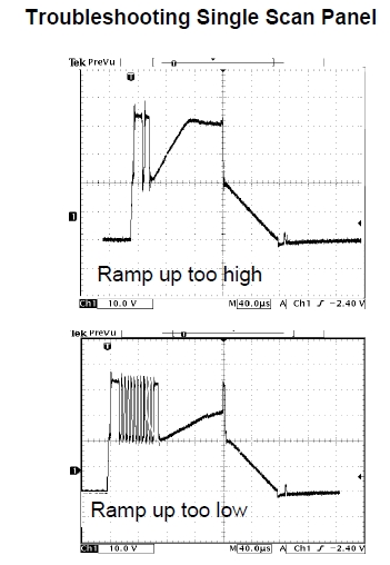
The external heatsunk mosfets DO get hot. The two parts ID'd as
900V operate in their linear mode to develop the ramps, using a >miller-cap/diode network between gate and drain. These two slopes
are visible on the sick puppy's panel drive waveforms.
I suppose that if the SUS_UP slope was slower and continuous,
then a ~ book waveform could be created, using the end of
drive period as the SUS-DN, per older 'return to -VY' methods.
The book timing (40us/div) suggests that SUS-UP and SUS_DN are
expected to complete in ~ (+)100us (-)80us time periods.
Sick puppy's SUS_UP (50us/div) is too quick. The components in
the 900V part's set-up miller network seem to be OK individually.
Maybe if it was slower, the waveform might magically turn into
a single pulse, rather than a double one. . . . . ?
RL
Still don't know why the buffer test point doesnt follow SUS_OUT.
I'm working with a dark screen - a few pin-pricks of colour
visible in a dark room.
On Wed, 06 Oct 2021 14:32:04 -0400, legg <le...@nospam.magma.ca> wrote:
<snip>
One of the 3 paralleled external fets had avalanched and gone
resistive between gate and drain to overload -VY. With this was
fixed, the buffer board seemed to pump -VY more negative than
its regulated -200V, increasing to -250V or more to put the
parallel fets into danger of avalanche). A new buffer board
prevented this.
The external heatsunk mosfets DO get hot. The two parts ID'd as
900V operate in their linear mode to develop the ramps, using a >miller-cap/diode network between gate and drain. These two slopes
are visible on the sick puppy's panel drive waveforms.
I suppose that if the SUS_UP slope was slower and continuous,
then a ~ book waveform could be created, using the end of
drive period as the SUS-DN, per older 'return to -VY' methods.
The book timing (40us/div) suggests that SUS-UP and SUS_DN are
expected to complete in ~ (+)100us (-)80us time periods.
Sick puppy's SUS_UP (50us/div) is too quick. The components in
the 900V part's set-up miller network seem to be OK individually.
Maybe if it was slower, the waveform might magically turn into
a single pulse, rather than a double one. . . . . ?
RL
Still don't know why the buffer test point doesnt follow SUS_OUT.
I'm working with a dark screen - a few pin-pricks of colour
visible in a dark room.
Replacing the buffer board stopped the pumping up of -VY.
A replacement control card got rid of the double/interrupted set-up
waveform, though this double set-up seems to be valid for some
dual-scan units. Waveform out of Y_SUS now bog-standard, but
buffer test pointstill not following Y_SUS negative.
This produced an illuminated panel with vertical red/white/yellow
bands playing wack-a-mole left-right and center - at random -
for a few minutes, until a resistor in an RCD network located
towards the top of the buffer board popped - leaving a horizontal
dark green band across the top of the screen; the rest dark.
Replacing the resistor and cap(presumed culprit) allowed for a
repeat performance; same picture sequencing; same 47R 1W smd
resistor popped in same location.
. . . so its not just a defective RCD snubber.
RL
On Friday, October 8, 2021 at 10:31:38 PM UTC-4, legg wrote:
On Wed, 06 Oct 2021 14:32:04 -0400, legg <le...@nospam.magma.ca> wrote:
<snip>
One of the 3 paralleled external fets had avalanched and goneReplacing the buffer board stopped the pumping up of -VY.
resistive between gate and drain to overload -VY. With this was
fixed, the buffer board seemed to pump -VY more negative than
its regulated -200V, increasing to -250V or more to put the
parallel fets into danger of avalanche). A new buffer board
prevented this.
The external heatsunk mosfets DO get hot. The two parts ID'd as
900V operate in their linear mode to develop the ramps, using a
miller-cap/diode network between gate and drain. These two slopes
are visible on the sick puppy's panel drive waveforms.
I suppose that if the SUS_UP slope was slower and continuous,
then a ~ book waveform could be created, using the end of
drive period as the SUS-DN, per older 'return to -VY' methods.
The book timing (40us/div) suggests that SUS-UP and SUS_DN are
expected to complete in ~ (+)100us (-)80us time periods.
Sick puppy's SUS_UP (50us/div) is too quick. The components in
the 900V part's set-up miller network seem to be OK individually.
Maybe if it was slower, the waveform might magically turn into
a single pulse, rather than a double one. . . . . ?
RL
Still don't know why the buffer test point doesnt follow SUS_OUT.
I'm working with a dark screen - a few pin-pricks of colour
visible in a dark room.
A replacement control card got rid of the double/interrupted set-up
waveform, though this double set-up seems to be valid for some
dual-scan units. Waveform out of Y_SUS now bog-standard, but
buffer test pointstill not following Y_SUS negative.
This produced an illuminated panel with vertical red/white/yellow
bands playing wack-a-mole left-right and center - at random -
for a few minutes, until a resistor in an RCD network located
towards the top of the buffer board popped - leaving a horizontal
dark green band across the top of the screen; the rest dark.
Replacing the resistor and cap(presumed culprit) allowed for a
repeat performance; same picture sequencing; same 47R 1W smd
resistor popped in same location.
. . . so its not just a defective RCD snubber.
RL
Get a bright light and go over the entire display slowly looking for a single burned pixel. If you find one, the display is junk. Not common on LG but not unheard of either.
. . . so its not just a defective RCD snubber.
RL
Get a bright light and go over the entire display slowly looking for a single burned pixel. If you find one, the display is junk. Not common on LG but not unheard of either.That would do it? - cause this repeated component failure?
Couldn't the connections to that single pixel be disconnected,
producing a black t on the screen, and non-popping parts?
RL
On Saturday, October 9, 2021 at 12:17:58 PM UTC-4, legg wrote:
That would do it? - cause this repeated component failure?. . . so its not just a defective RCD snubber.
RL
Get a bright light and go over the entire display slowly looking for a single burned pixel. If you find one, the display is junk. Not common on LG but not unheard of either.
Couldn't the connections to that single pixel be disconnected,
producing a black t on the screen, and non-popping parts?
RL
Yes. Learned from experience. I never touched a plasma until I carefully went over the entire display, including right to the edges. A single burned pixel meant the end of the road.
I repaired at least a hundred of those series when I was an LG ASC. The vast majority were bad IPMs on one sustain or the other, and once in a while a bad buffer board. I don't recall ever seeing a bad control, main, or power supply.
On Mon, 11 Oct 2021 13:19:51 -0700 (PDT), "ohg...@gmail.com" <ohg...@gmail.com> wrote:
On Saturday, October 9, 2021 at 12:17:58 PM UTC-4, legg wrote:
That would do it? - cause this repeated component failure?. . . so its not just a defective RCD snubber.
RL
Get a bright light and go over the entire display slowly looking for a single burned pixel. If you find one, the display is junk. Not common on LG but not unheard of either.
Couldn't the connections to that single pixel be disconnected,
producing a black t on the screen, and non-popping parts?
RL
Yes. Learned from experience. I never touched a plasma until I carefully went over the entire display, including right to the edges. A single burned pixel meant the end of the road.
I repaired at least a hundred of those series when I was an LG ASC. The vast majority were bad IPMs on one sustain or the other, and once in a while a bad buffer board. I don't recall ever seeing a bad control, main, or power supply.
I came across a service advisory for this model that
gave me a chuckle:
"2006 LCD, PDP, & MDPs that use the ARM CPU & Micronix Flash Memory.
Symptom:
During a specific date range the customer may turn on the TV and there
will be no video
or audio. The problem will first occur: Jun 20th, 2006, 14:03 ~ Jun
21st, 08:14. Then
it repeats every 194 days.
Solution:
Temporary fix is a hard reset (unplug for a few seconds). New firmware
is available as
a permanent fix. The update needs to be done by a service center.
Models:
32LC2D, 37LC2D, 42LC2D, 42PC3DV, 42PC3DVA, 42PC3D, 50PC3D, 50PX2D,
50PX2DC.
Tools Required:
Computer
Null Modem Serial Cable
Tools Supplied:
Instructions
Firmware Files
DTVLab Update Software
Versions:
32LC2D-UD : Ver3.06.1
37LC2D-UD : Ver3.06.1
42LC2D-UD : Ver3.05.1
42PC3DV-UD(42PC3DVA-UD) : Ver3.06.1
42PC3D-UD : Ver3.07.1
50PC3D-UD : Ver3.07.1
50PX2D-UD(50PX2DC-UD) : Ver3.10.1
42PC3DV-UD,42PC3DVA-UD : the same as S/W
50PX2D-UD,50PX2DC-UD : the same as S/W "
Would have thought that such an advisory would have
generated a surplus of support tools that would
remain for later employment . . . but nada.
RL
On Tuesday, October 12, 2021 at 10:24:56 AM UTC-4, legg wrote:
On Mon, 11 Oct 2021 13:19:51 -0700 (PDT), "ohg...@gmail.com"
<ohg...@gmail.com> wrote:
On Saturday, October 9, 2021 at 12:17:58 PM UTC-4, legg wrote:I came across a service advisory for this model that
That would do it? - cause this repeated component failure?. . . so its not just a defective RCD snubber.
RL
Get a bright light and go over the entire display slowly looking for a single burned pixel. If you find one, the display is junk. Not common on LG but not unheard of either.
Couldn't the connections to that single pixel be disconnected,
producing a black t on the screen, and non-popping parts?
RL
Yes. Learned from experience. I never touched a plasma until I carefully went over the entire display, including right to the edges. A single burned pixel meant the end of the road.
I repaired at least a hundred of those series when I was an LG ASC. The vast majority were bad IPMs on one sustain or the other, and once in a while a bad buffer board. I don't recall ever seeing a bad control, main, or power supply.
gave me a chuckle:
"2006 LCD, PDP, & MDPs that use the ARM CPU & Micronix Flash Memory.
Symptom:
During a specific date range the customer may turn on the TV and there
will be no video
or audio. The problem will first occur: Jun 20th, 2006, 14:03 ~ Jun
21st, 08:14. Then
it repeats every 194 days.
Solution:
Temporary fix is a hard reset (unplug for a few seconds). New firmware
is available as
a permanent fix. The update needs to be done by a service center.
Models:
32LC2D, 37LC2D, 42LC2D, 42PC3DV, 42PC3DVA, 42PC3D, 50PC3D, 50PX2D,
50PX2DC.
Tools Required:
Computer
Null Modem Serial Cable
Tools Supplied:
Instructions
Firmware Files
DTVLab Update Software
Versions:
32LC2D-UD : Ver3.06.1
37LC2D-UD : Ver3.06.1
42LC2D-UD : Ver3.05.1
42PC3DV-UD(42PC3DVA-UD) : Ver3.06.1
42PC3D-UD : Ver3.07.1
50PC3D-UD : Ver3.07.1
50PX2D-UD(50PX2DC-UD) : Ver3.10.1
42PC3DV-UD,42PC3DVA-UD : the same as S/W
50PX2D-UD,50PX2DC-UD : the same as S/W "
Would have thought that such an advisory would have
generated a surplus of support tools that would
remain for later employment . . . but nada.
RL
Honestly, I don't remember that at all. If I read that bulletin, then I forgot about it. I also don't recall ever getting complaints about that problem.
On Tue, 12 Oct 2021 09:17:51 -0700 (PDT), "ohg...@gmail.com" <ohg...@gmail.com> wrote:
On Tuesday, October 12, 2021 at 10:24:56 AM UTC-4, legg wrote:
On Mon, 11 Oct 2021 13:19:51 -0700 (PDT), "ohg...@gmail.com"
<ohg...@gmail.com> wrote:
On Saturday, October 9, 2021 at 12:17:58 PM UTC-4, legg wrote:I came across a service advisory for this model that
That would do it? - cause this repeated component failure?. . . so its not just a defective RCD snubber.
RL
Get a bright light and go over the entire display slowly looking for a single burned pixel. If you find one, the display is junk. Not common on LG but not unheard of either.
Couldn't the connections to that single pixel be disconnected,
producing a black t on the screen, and non-popping parts?
RL
Yes. Learned from experience. I never touched a plasma until I carefully went over the entire display, including right to the edges. A single burned pixel meant the end of the road.
I repaired at least a hundred of those series when I was an LG ASC. The vast majority were bad IPMs on one sustain or the other, and once in a while a bad buffer board. I don't recall ever seeing a bad control, main, or power supply.
gave me a chuckle:
"2006 LCD, PDP, & MDPs that use the ARM CPU & Micronix Flash Memory.
Symptom:
During a specific date range the customer may turn on the TV and there
will be no video
or audio. The problem will first occur: Jun 20th, 2006, 14:03 ~ Jun
21st, 08:14. Then
it repeats every 194 days.
Solution:
Temporary fix is a hard reset (unplug for a few seconds). New firmware
is available as
a permanent fix. The update needs to be done by a service center.
Models:
32LC2D, 37LC2D, 42LC2D, 42PC3DV, 42PC3DVA, 42PC3D, 50PC3D, 50PX2D,
50PX2DC.
Tools Required:
Computer
Null Modem Serial Cable
Tools Supplied:
Instructions
Firmware Files
DTVLab Update Software
Versions:
32LC2D-UD : Ver3.06.1
37LC2D-UD : Ver3.06.1
42LC2D-UD : Ver3.05.1
42PC3DV-UD(42PC3DVA-UD) : Ver3.06.1
42PC3D-UD : Ver3.07.1
50PC3D-UD : Ver3.07.1
50PX2D-UD(50PX2DC-UD) : Ver3.10.1
42PC3DV-UD,42PC3DVA-UD : the same as S/W
50PX2D-UD,50PX2DC-UD : the same as S/W "
Would have thought that such an advisory would have
generated a surplus of support tools that would
remain for later employment . . . but nada.
RL
Honestly, I don't remember that at all. If I read that bulletin, then I forgot about it. I also don't recall ever getting complaints about that problem.After replacing the 74AC540s on the YSUS board, a 2nd buffer
board replacement didn't pop it's top 47R resistor - although
I'm only running the device long enough to scope a few waveforms
and take a few screen shots - so I don't know for sure whether
the resisisor or a similar part will fail again, given the
opportunity.
The buffer output voltage still does not follow the YSUS output
below about -50V.
http://ve3ute.ca/query/42PC3D_2nd_buffer_board_211112-005.jpg http://ve3ute.ca/query/42PC3D_2nd_buffer_board_211112-010.jpg
I now get a lit panel with greenish horizontal streaks and a
red-yellowish vertical section that hops back and forth across
the display. This was what I was looking at for very short
time periods, previously, before the buffer board resistor
failure blanked out the bottom sections.
http://ve3ute.ca/query/42PC3D_2nd_buffer_board_211112P0009.JPG
Do I need a white screen (or any) input signal to go further?
Most TV's have a built-in "no signal source detected' display
pattern . . .
RL
After replacing the 74AC540s on the YSUS board, a 2nd buffer
board replacement didn't pop it's top 47R resistor - although
I'm only running the device long enough to scope a few waveforms
and take a few screen shots - so I don't know for sure whether
the resisisor or a similar part will fail again, given the
opportunity.
The buffer output voltage still does not follow the YSUS output
below about -50V.
http://ve3ute.ca/query/42PC3D_2nd_buffer_board_211112-005.jpg
http://ve3ute.ca/query/42PC3D_2nd_buffer_board_211112-010.jpg
I now get a lit panel with greenish horizontal streaks and a
red-yellowish vertical section that hops back and forth across
the display. This was what I was looking at for very short
time periods, previously, before the buffer board resistor
failure blanked out the bottom sections.
http://ve3ute.ca/query/42PC3D_2nd_buffer_board_211112P0009.JPG
Do I need a white screen (or any) input signal to go further?
Most TV's have a built-in "no signal source detected' display
pattern . . .
RL
The TV will produce an "input" legend at the the top of the screen
when it's turned on, and a "no signal" message will appear after
about 10 seconds of no signal. The TV's control board most likely
has a built in pattern generator that will help isolate a no
image complaint to either the main or control board assuming the
rest of the boards are working. It's been a long time since I
repaired those tanks so my memory isn't great on them - but if the
control board has a separate harness that plugs into the power
supply, the procedure was to remove the connector from the control
to the main and jump two pins on the control board. That would put
it in a pattern mode. I'm pretty sure I tossed all the training
manuals for those but I'll check next week when I get back to the shop.
a no image complaint to either the main or control board assuming the rest of the boards are working. It's been a long time since I repaired those tanks so my memory isn't great on them - but if the control board has a separate harness that plugs intoI now get a lit panel with greenish horizontal streaks and a
red-yellowish vertical section that hops back and forth across
the display. This was what I was looking at for very short
time periods, previously, before the buffer board resistor
failure blanked out the bottom sections.
http://ve3ute.ca/query/42PC3D_2nd_buffer_board_211112P0009.JPG
Do I need a white screen (or any) input signal to go further?
Most TV's have a built-in "no signal source detected' display
pattern . . .
RL
The TV will produce an "input" legend at the the top of the screen when it's turned on, and a "no signal" message will appear after about 10 seconds of no signal. The TV's control board most likely has a built in pattern generator that will help isolate
| Sysop: | Keyop |
|---|---|
| Location: | Huddersfield, West Yorkshire, UK |
| Users: | 481 |
| Nodes: | 16 (2 / 14) |
| Uptime: | 30:27:09 |
| Calls: | 9,544 |
| Calls today: | 4 |
| Files: | 13,656 |
| Messages: | 6,140,869 |